


Current measuring station TIS-3
In 2009-2010, we have upgraded the set of equipment at receiving measuring sites through installation of new measuring stations IS-2 with improved technical and operational characteristics. The accuracy of synchronization of receiving stations operation with operation of electropulse sounding plant ERGU-600 and the quality of recorded data have increased. The TIS-2 current measuring station which is a part of ERGU-600 and which was developed and made in 2005, failed to meet the new technical and operational requirements. Therefore, there appeared a need to improve the units of the ERGU-600 system. The modern hardware components together with new circuit solutions helped to eliminate the shortcomings of the previous current station and to considerably improve its parameters during development and construction of the modernized current measuring station TIS-3. Among the most significant innovations are:
- Increasing of the number of measuring path channels up to two and broadening of the bandwidth which enable to record not only current pulses in sounding dipole, but also voltage values it its terminals;
- Using of a faster PC as a part of the measuring complex;
- Increasing of sampling rate of analog-digital converters in the measuring station, and increasing of time of continuous signal recording;
- Replacement of old GPS-receivers by more reliable and accurate new receivers.
Major technical specifications of TIS-3:
Range of measured currents……….........................................…..5 - 1000 А (0,005 - 1,0 V)
Number of measuring channels ………....................................................................…..2
Bandwidth of measuring channels………..........................………….(0 – 200) Hz
Relative error of measuring the current pulse amplitude readings, no more .....…± 0,1%
Sampling rate of measured signal…................................................…….800 Hz
Time of continuous signal recording, no more…......................................…360 min
Capacity of analog-digital converter ..................................................24 bit
Repetition rate of TIS-3 output pulses for external synchronization of ERGU-600……….
..........................................................(10,24 ± 10-8) kHz
Error of time binding of triggering signal edge for ERGU-600 to absolute time of triggering
……………………............…….........2 mcs
Fig.12 shows the structure of TIS-3 station as a part of ERGU-600. Block of electronics, GPS-receiver and PC of TIS-3 station (fig.13) are located at sufficient distance (about
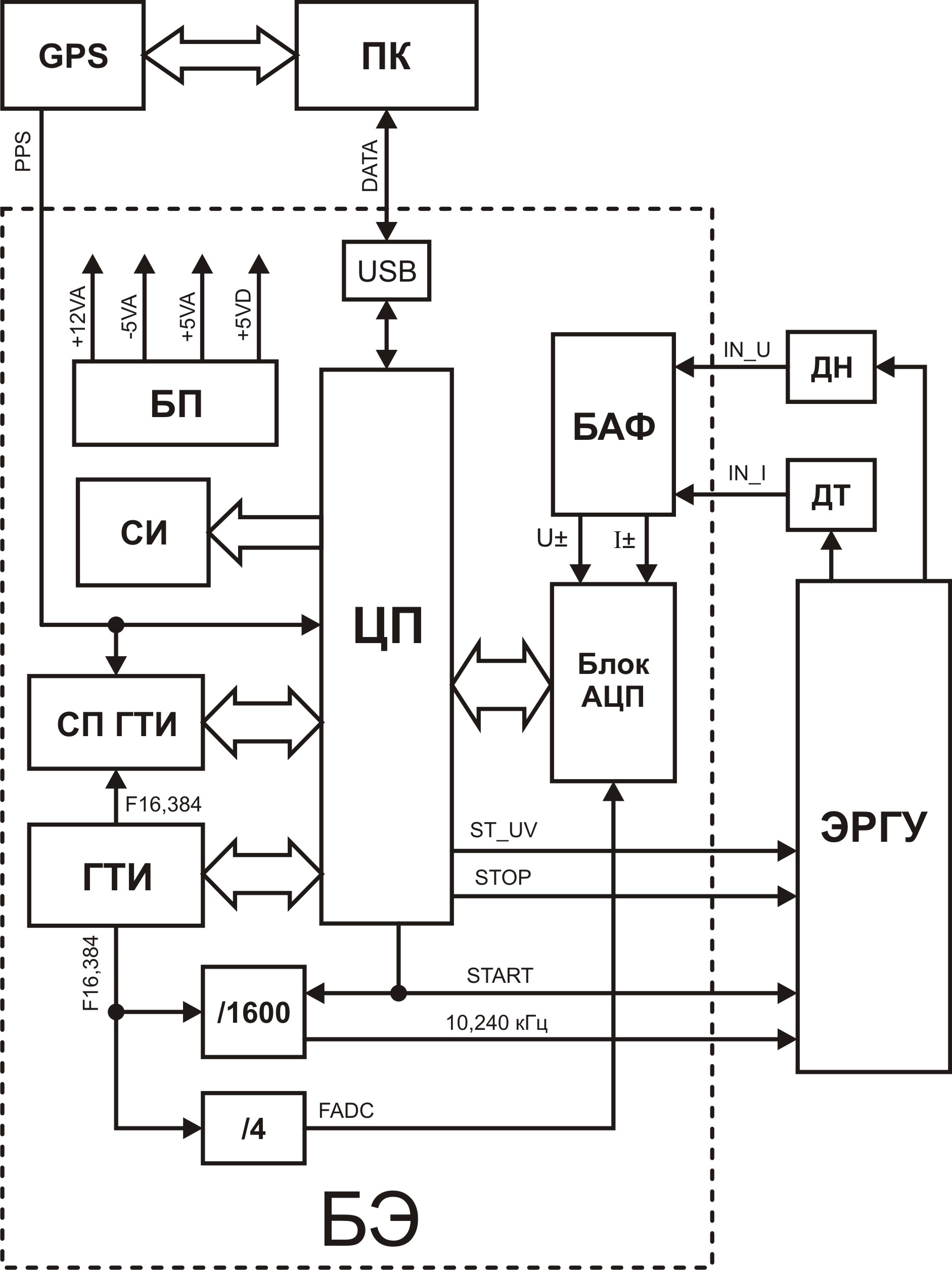
Fig. 12. Structural scheme of TIS-3 as a part of ERGU-600:
GPS – GPS receiver;
ПК – personal computer;
БЭ – electronics block;
БП – power supply unit;
ЦП – central processor;
БАФ – block of analog filtration;
ДН – voltage sensor;
ДТ – current sensor;
СИ – display circuit;
ГТИ – clock pulse generator;
СП ГТИ – adjustment scheme of clock pulse generator;
Блок АЦП – block of analog-digital conversion;
/1600 – frequency demultiplier by 1600;
/4 – frequency demultiplier by 4;
ЭРГУ – electropulse system ERGU–600.
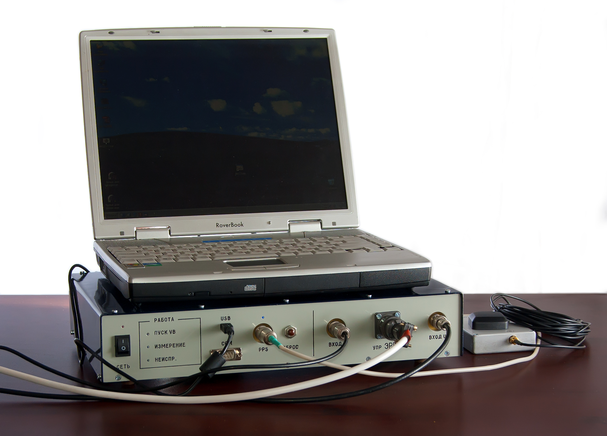
Fig. 13. Current measuring station TIS-3 (block of electronics, GPS-receiver, PC)
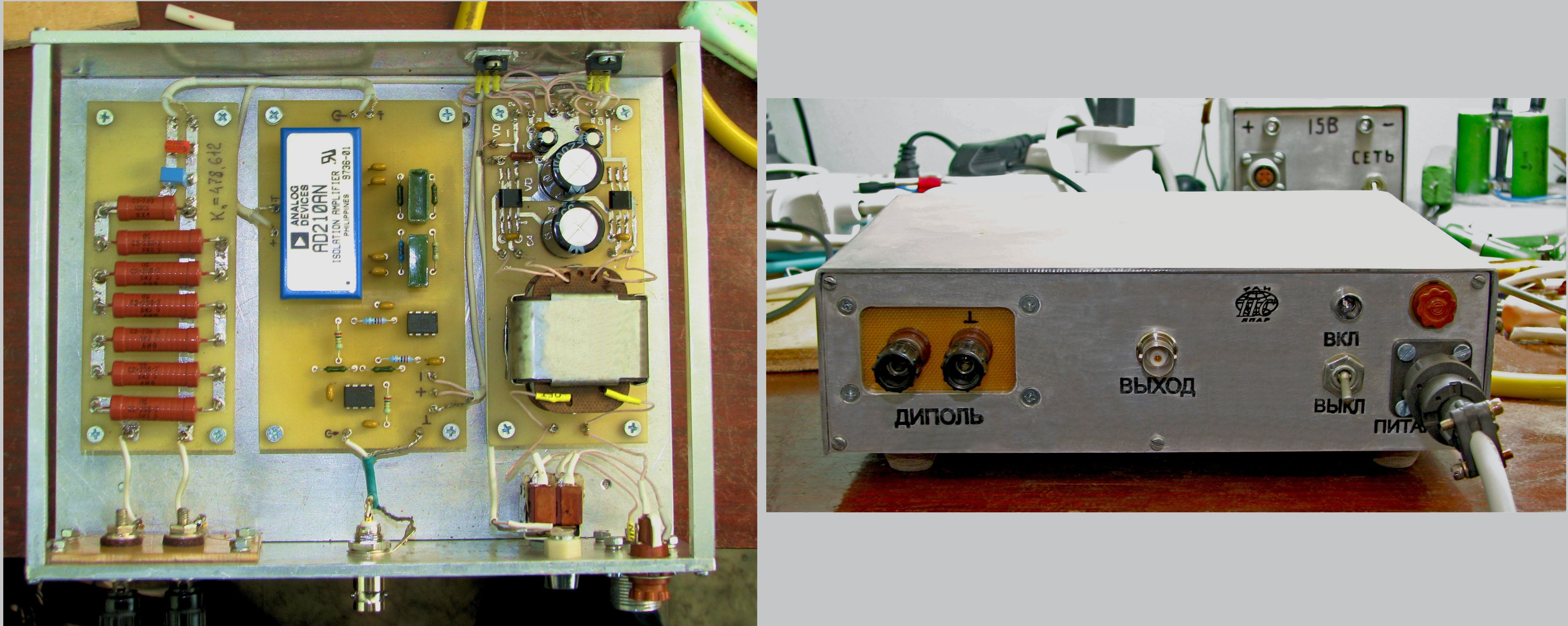
Fig.14. Current measuring station TIS-3, voltage sensor


