


Acoustic Emission Measuring Complex
Development and construction of Acoustic Emission Measuring Complex were carried out within the frameworks of the agreement with the Institute For High Energy Densities RAS on the subject “Development of methods of artificial relaxation of tectonic stresses in the Earth’s crust and reduction of seismic risk”.
The complex was developed and constructed on the order of the Laboratory of Energy-Saturated Media Simulation. The complex is designed to study processes in the depths of the Earth’s crust by the method of physical modeling using acoustic emission (AE) of loaded rock samples with weak external energy actions. Fig. 7 shows the structure of the complex.
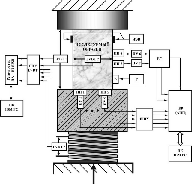
Fig. 7
ПП1÷ПП7 – primary piezoelectric converters of AE signals;
ПУ1÷ПУ7 - preliminary amplifiers of AE signals;
LVDT1÷LVDT2 – sensors of linear displacement;
БПУ LVDT – block of transformation and amplification of signals of LVDT sensors;
БШУ – block of broadband amplifiers;
БР(АЦП) – block of registration (analog-digital converters);
БС – synchronization block;
ПК IBM PC – personal computer;
ИЭВ – source of electric impacts;
Г – low-frequency generator;
В – vibrator (buzzer);
The measuring complex consists of seven channels for registration of signals of acoustic emission of rock samples; five measuring channels for registration of components of rock samples deformation and one channel for registration and control of value of main load (compression force). Measuring equipment can be placed on different plants (special rheological presses). For such experiments, the Research Station RAS uses spring rheological plant for long run tests constructed by A.N.Stavrogin (All-Russian Research Institute of Mining Geomechanics and Survey, Saint-Petersburg) with maximal compressive load up to 100 ton, the rheological stand with long-travel spring which ensures the compression of sample with the force up to 20 ton, and the lever press with maximal compressive force about 60 ton. The two last plants were designed and made at the Research Station RAS.
For detection, record and further calculation of AE signals flow parameters in the measuring complex, the two measuring channels are used. They consist of primary converters of AE signals (ПП6, ПП7), preliminary amplifiers (ПУ6, ПУ7), synchronization block (БС), and also two high-speed analog-digital converters (ADC) which are the part of the block of registration (БР) of acoustic signals.
The synchronization block (fig. 8) ensures amplification, frequency filtering and detection of signals arriving to its input from primary converters of AE signals (ПП6, ПП7) amplified by preliminary amplifiers (ПУ6, ПУ7). Preliminary amplifiers are located in close vicinity to primary piezoelectric transducers and unsure primary amplification (≈ 20 dB) of AE signals and their transmission to a considerable distance (up to
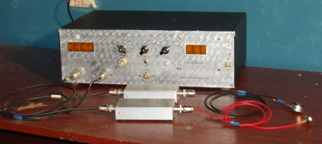
Fig 8. Synchronization block with detachable preliminary amplifiers and attached primary piezoelectric transducers of acoustic emission.
As ПП6 and ПП7 we used broadband piezoelectric transducers of acoustic signals (SE2MEG) produced by DECI Company (USA) which were fastened on the lateral face of investigated sample.
One of the measuring channels is a reference channel which is used to detect AE signals. To improve the characteristics of signal detection such as false-alarm probability and right detection probability, and also to reduce the influence of noise and stray coupling, the passband in this channel was chosen consistent with the expected spectrum of AE signals (100 ÷ 900 kHz).
While locating the AE sources, the measuring system uses five measuring channels which consist of five spaced AE sensors (ПП1, ПП5, ПУ1, ПУ5) and the six-channel (one reserve channel) block of broadband noiseless amplifiers (БШУ)
Location of AE sources is performed by time delays between the recorded AE signals. To ensure the mode of AE location we developed and constructed special broadband sensors of acoustic emission with built-in preliminary amplifiers which are in the form of acoustic antenna array and are located in the bottom base plate of the press with a good acoustic contact with the investigated sample. The distinctive feature of these sensors is that the primary converter is galvanically untied from the bearing structure of the testing plant, and the preliminary amplifier is compatible with the primary converter and does not require a separate bus for power supply (power buses are combined with the lines of output signal). This made it possible to considerably decrease the influence of external electromagnetic stray coupling and noise.
The six-channel block of broadband amplifiers (БШУ, fig.9) is designed for further amplification and filtration of signals arriving from the outputs of preliminary amplifiers (ПУ1¸ ПУ5). The distinctive feature of the block is the presence of three outputs in each amplifier which differ in amplification (10 dB between neighboring outputs) which makes it possible to increase the dynamic range of recorded signals up to 80 dB.
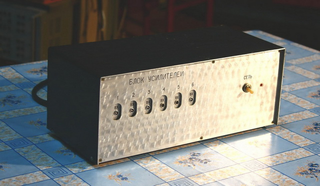
Fig. 9
The block of registration for AE signals (БР) has a set of fast-acting analog-digital converters ФК4224, ФК4225 and ФК4226 which are controlled by a special controller in CAMAC standard. The built-in circular buffers of memory along with external launch and clocking ensure synchronous multichannel registration of pulse AE signals keeping records of prehistory of each AE event. During signal processing, the recorded prehistory of AE events allows determining the parameters of first arrival of pulse AE signals. After the completion of record cycle (filling in of memory buffer), the recorded data are transferred to the external computer for further processing.
The analog-digital converters (ADC) are connected to the external computer via special CAMAC-controller. The measuring system has a standby mode of AE signals registration. The readings of AE signals are recorded to ADC buffer until it becomes full provided that the signal exceeds the level of preset threshold which meets the conditions of amplitude sampling (detection). After the buffer is full, the information is transferred to external computer and then the system returns to standby mode. Such recording mode allows saving of external computer memory.
The measuring complex has six measuring channels to control and measure the values of major mechanical stress (load) and deformation components (longitudinal and lateral) of investigated samples. As sensors of deformation and load in these channels we use Schaevitz Company’s (
To measure each of the orthogonal components of lateral deformation, we use two LVDT transducers which control horizontal displacement of the two opposite sides of the sample relative to the fixed bearing. The deformation component is determined as a difference (adjusted for sign) of displacements measured by these transducers. Fig. 7 shows the transducer of one of lateral deformation components (LVDT2) which controls the difference of displacements of lateral sides of the sample. Signals from deformation and load transducers arrive to the input of specially developed and constructed six-channel block of transformation and amplification БПУ LVDT (fig. 10).
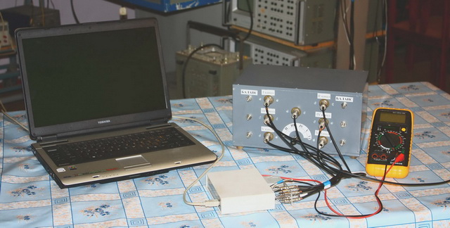
Fig. 10
Fig. 11 shows structure of the БПУ LVDT channel. БПУ LVDT ensures the formation of reference sinusoidal signals of preset frequency and amplitude transmitted to LVDT transducers, transformation (demodulation) of output signals of transducers, as well as their amplification and low-frequency filtering. Special circuit and construction methods and solutions used in the process of development along with using of modern elements base and choosing of optimal parameters of measuring scheme made it possible to achieve high accuracy of measuring of controlled parameters. The absolute error of load measurement was no more than ± 10 kHz, and deformation – no more than ± 0,2 mkm.
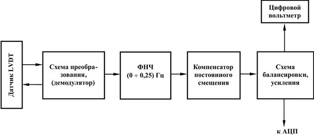
Fig. 11. Structure of БПУ LVDT measuring channel.
The following facilities were used as sources of additional electromagnetic actions on investigated samples in the measuring complex:
1. Pulse generator Г5-54 which forms rectangular pulses with amplitude about 50V. Pulse duration was about 5 , 10 microseconds, the repetition rate changed between 1 and 3 kHz;
2. Induction spark-gap generator which forms pulses with amplitude up to 10 kB (pulse shape not controlled);
3. Condenser discharger which forms electric pulses with steepness of pulse edge about 1 mcs and peak voltage about 1 kV.
Signals from sources of external electric actions are supplied to carbon electrodes fixed on the surface of investigated sample.
For vibroactions in the measuring system we used a special small vibrator (B) constructed in the form of piezoceramic transducer (buzzer) fixed on one side of investigated sample. On electrical clips of buzzer we applied sinusoidal signal with preset frequency and amplitude from low-frequency generator (Г) ensuring the required level and frequency of vibrations.
Since 2001, the measuring complex has been used in a large series of experiments on registration of acoustic emission of geomaterials in the presence of additional physical fields applied externally. We have tested more than 20 rock samples, more than 10 samples specially made from cement-granite mixture, and also several samples from zirconium ceramics. In general, more than 30000 AE signals were recorded in our experiments. These measurements have confirmed the adequacy of the equipment to the investigated phenomenon of AE response to action of physical fields.
We have developed a special software kit for processing of recorded signals. The purpose of processing is to receive characteristics of certain AE signals, as well as characteristics of AE events flow.
The results of registration and processing of AE signals were used to create a representative base of acoustic emission data which reflect the influence of electromagnetic fields and vibrations on deformation processes.


